AS440 AUTOMATIC VOLTAGE REGULATOR
General description
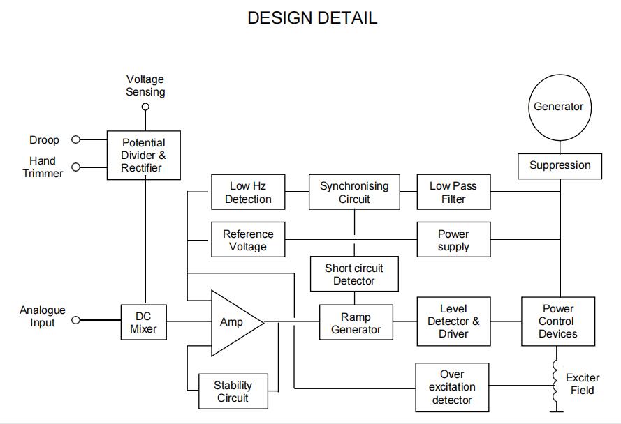
AS440 is a half wave phase controlled thyristor type AVR and forms part of the excitation system for a brushless generator.
The design employs Surface Mount Technology (SMT) for high integration of features in a small footprint AVR.
Positive voltage build up from residual levels is ensured by the use of efficient semiconductors in the power circuitry of the AVR.
The power and voltage sensing circuits have separate terminals, allowing the excitation power to be derived directly from the stator
winding for basic applications or from an auxiliary winding if sustained short circuit performance is required.
The AVR is linked with the main stator windings and the exciter field windings to provide closed loop control of the output voltage with load
regulation of +/- 1.0%. The AVR voltage sensing terminals continuously sample the output windings for voltage control purposes.
In response to this sample voltage, the AVR controls the power fed to the exciter field, and hence the main field, to maintain the
machine output voltage within the specified limits, compensating for load, speed, temperature and power factor, of the generator.

Technical specification
SENSING INPUT
Voltage Jumper selectable
100-130 Vac 1 phase or
190-264 Vac 1 phase
Frequency 50-60 Hz nominal
POWER INPUT
Voltage 100-264 V ac 1 phase
Frequency 50-60 Hz nominal
OUTPUT
Voltage 82 V d.c. @ 200 V a.c.
Current continuous 4A (see note 1).
transient 7.5A for 10 secs.
Resistance 15 ohms min
(10 ohms min when input
volts is less than 175 ac)

REGULATION
+/- 1.0% (see note 2)
THERMAL DRIFT
0.03% per deg. C change in AVR ambient (see note 3)
TYPICAL SYSTEM RESPONSE
AVR response 20 ms
Filed current to 90% 80 ms
Machine Volts to 97% 300 ms
EXTERNAL VOLTAGE ADJUSTMENT
+/-10% with 1 k ohm 1 watt trimmer (see note 4)
Increasing resistance lowers voltage.
UNDER FREQUENCY PROTECTION
Set point 94 -98% Hz (see note 5)
UNIT POWER DISSIPATION
12 watts maximum
BUILD UP VOLTAGE
4 Volts @ AVR terminals
ANALOGUE INPUT
Maximum input +/- 5 Vdc (see note 6)
Sensitivity 1V for 5% Generator Volts (adjustable)
Input resistance 1k ohm
QUADRATURE DROOP INPUT
10 ohms burden
Max. sensitivity: 0.07 A for 5% droop 0PF
Max. input: 0.33 A
OVER EXCITATION PROTECTION
Set point 65 V dc
Time delay 10-15 seconds (fixed)
ENVIRONMENTAL
Vibration 20-100 Hz 50mm/sec
100Hz – 2kHz 3.3g
Operating temperature -40 to +70C (note 7)
Relative Humidity 0-70C 95% (note 8)
Storage temperature -55 to +80C
NOTES
1. De-rate by 12% if mounted in ‘portrait’ orientation.
2. With 4% engine governing.
3. After 2 minutes.
4. Generator de-rate may apply. Check with factory.
5. Factory set, semi-sealed, jumper selectable.
6. Any device connected to the analogue input must be fully
floating (galvanically isolated from ground), with an
insulation strength of 500V ac.
7. De-rate output current by 5% per degree C above 60C.
8. Non condensing
|
SUMMARY OF AVR CONTROLS
|
||
|
CONTROL
|
FUNCTION
|
DIRECTION
|
|
VOLTS
STABILITY
STAB SWITCH
UFRO
DROOP
EXC TRIP
|
TO ADJUST GENERATOR OUTPUT VOLTAGE
TO PREVENT VOLTAGE HUNTING
TO OPTIMISE TRANSIENT PERFORMANCE
TO SET THE UFRO KNEE POINT
TO SET THE GENERATOR DROOP TO 5% AT 0PF
TO OPTIMISE ANALOGUE INPUT SENSITIVITY
TO SET OVER EXCITATION TRIP CUT OFF LEVEL
|
CLOCKWISE INCREASES OUTPUT VOLTAGE
CLOCKWISE INCREASE THE DAMPING EFFECT
SEE TABLE ABOVE
CLOCKWISE REDUCES THE KNEE POINT FREQUENCY
CLOCKWISE INCREASES THE DROOP
CLOCKWISE INCREASES THE GAIN OR SENSITIVITY
CLOCKWISE INCREASES THE CUT OFF LEVEL
|
Intelligent Digital Charger ZH-CH2830
Chinese New Year Holiday Notice